This posts provides a (very rough) sketch for a virtual machine such that execution of arbitrary programs on this machine can be verified with a single STARK. To make the VM practical, the instruction set is not Turing-complete but I think it may still be powerful enough to cover a large set of smart contract use cases.
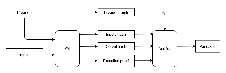
The diagram below illustrates the basic concept:
In the above:
- The VM does the following:
a. Takes 2 inputs: a program and a set of inputs for the program,
b. Executes the program with the given set of inputs,
c. Outputs hash of the inputs, hash of the outputs generated by the program, and a STARK proof attesting to the correct execution of the program. - The verifier does the following:
a. Takes the hash of the program, hash of the inputs, and hash of the outputs, and uses them to verify the STARK proof.
Potential advantages of this approach:
- The program, the inputs, and the outputs are fully private (they are never revealed to the verifier).
- A single verifier can verify any program executed on the VM (e.g. a verifier can be a single on-chain contract).
- Since the structure of the STARK is the same for all programs, batching of proofs using another STARK (or a SNARK) should be much easier to accomplish.
In terms of execution speed, my very rough gestimate is that an optimized prover on a CPU with several cores should be able to get to about 1 KHz (1,000 instructions / second), and with specialized hardware it may be possible to get to some MHz.
Just to say it again: this is a very rough sketch and the description below is by no means complete. It should be enough to illustrate the basic ideas though, and I’m curious if anyone sees any major issues with these.
vm overview
At the highest level, the VM is a stack machine. The execution trace consists of several sets of registers each having a separate function as shown below:
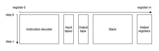
- Instruction decoder is perhaps the “heaviest” part of the trace. It is responsible for decoding instructions into their binary representation and building a continuous hash of the executed instructions. It would require roughly 14 registers.
- Input tapes - there would be two input tapes. One of the tapes will contain inputs to be pushed onto the stack, and the other tape with “hints” to aid in execution of certain instructions. Similar to program instructions, the input tape is contentiously hashed so that by the end of the execution the tape is reduced to a single hash value.
- Output tape - this would be the tape that defines output values of the program. Though, there might be better ways to handle outputs.
- Stack registers will represent the stack with the first register being the top of the stack, the second register being the second from the top etc. It is important to note that the number of stack registers does not need to be fixed. Without loss of generality, it can be set to any reasonable number as required by a specific program (e.g. 4, 20, 80). This is because traces of all “unused” stack registers are just zeros, and this can be succinctly communicated to the verifier.
- Helper registers would be a small set of registers (e.g. 3 - 5) which could aid in execution of certain complex instructions (e.g. hashing, elliptic curve operations).
Overall, my guess would be that a typical program might require 30 - 40 registers, though, I might be very off on this.
Here is an example of how an execution trace of a program could look like. It omits and simplifies a lot of details, but should illustrate the concept:
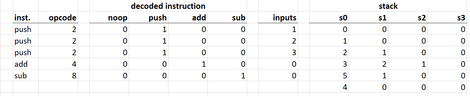
Here is what’s happening here:
- First, values
1,2, and3are pushed onto the stack. - Then, top two values are popped from the stack, added, and the result is pushed back onto the stack.
- Lastly, top two values are popped from the stack, the second value is subtracted from the first, and the result is pushed back onto the stack.
A transition function for the above could be simply described as follows:
where:
- s_n and s_{n+1} are the current and the next states of the stack.
- d_i are the bits of decoded instruction.
This is a somewhat inefficient way to describe the transition function. In reality, there wouldn’t be a single register per instruction, but rather a combination of several registers would be used to encode all instructions. However, there still would be a single transition function per instruction, and a combination of all instruction-specific transition functions would describe the VM transition function. The number of instructions could be kept relatively small (e.g. 40) and the degree of the VM transition function does no need to exceed 8.
programs
One of the challenges of defining a VM such that a single STARK can be used to prove execution of an arbitrary program is handling of conditional branches. One simple way to handle these is to decompose the program into all possible linear execution paths and put these paths into a Merkle tree (this approach is somewhat similar to Merkelized Abstract Syntax trees). Here is an example:
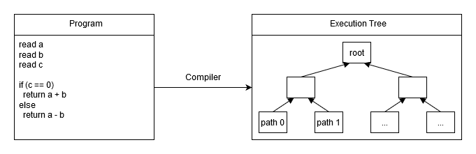
In the above:
path 0might bepush push push assertZero addpath 1might bepush push push assertNotZero sub
The biggest limitation of this approach is that programs with deep conditional logic become impractical, and some programs (e.g. with unbounded loops) become impossible. Realistically speaking, programs with over a million possible execution paths are probably too complex and this can be reached with about 20 nested (or consecutive) if/else statements. There might be some ways to mitigate this limitation - though, I haven’t come up with any yet.
One possible (though probably rather weak) advantage of this approach, is that the explicit need to list all possible execution paths can help with formal verification of the program.
instruction set
The instructions could be encoded as 8-bit values (other approaches are possible, though, 8-bit representation has a number of advantages). These 8 bits could be split into 2 sets:
- 3 bits to encode 7 “high-degree” instructions - i.e. instructions of degree 4 or 5
- 5 bits to encode 31 “low-degree” instructions - i.e. instructions of degree 3 or lower
This in total gives a set of 38 possible instructions (though again, this could be changed if needed). Here is a list of some of the possible instructions:
| Instruction | Description | Degree | Alignment | Steps |
|---|---|---|---|---|
| noop | do nothing | 1 | 1 | 1 |
| verify | fail if top of the stack is not 0 | 1 | 1 | 1 |
| push | push input onto the stack | 1 | 1 | 1 |
| pop | remove value from the top of the stack | 1 | 1 | 1 |
| swap | swap top 2 values of the stack | 1 | 1 | 1 |
| dup | duplicate top stack value | 1 | 1 | 1 |
| add | pop top 2 values, add them, push the result onto the stack | 1 | 1 | 1 |
| sub | pop top 2 values, subtract second from first, push the result onto the stack | 1 | 1 | 1 |
| mul | pop top 2 values, multiply them, push the result onto the stack | 1 | 1 | 1 |
| div | pop top 2 values, divide first by second, push the result onto the stack | ? | 1 | 1 |
| eq | pop top 2 values, compare them, and push 1 if they are equal, 0 otherwise | ? | 1 | 1 |
| neq | pop top 2 values, compare them, and push 0 if they are equal, 1 otherwise | ? | 1 | 1 |
| lt | pop top 2 values, compare them, and push 1 if first is less than second, 0 otherwise | ? | 256 | 256 |
| gt | pop top 2 values, compare them, and push 0 if first is less than second, 1 otherwise | ? | 256 | 256 |
| phash_1 | pop top stack value, hash it using Poseidon hash function, push the result onto the stack | 5 | 64 | 64 |
| phash_2 | pop top 2 values, hash them using Poseidon hash function, push the result onto the stack | 5 | 64 | 64 |
| rhash_1 | pop top stack value, hash it using Rescue hash function, push the result onto the stack | 3 | 32 | 32 |
| rhash_2 | pop top 2 values, hash them using Rescue hash function, push the result onto the stack | 3 | 32 | 32 |
| ec_add | pop top 4 values, interpret them as x, y coordinates of 2 elliptic curve points, add the points, and push the resulting x, y coordinates onto the stack | 4 | 2 | 1 |
| ec_dub | pop top 2 values, interpret them as x, y coordinates of an elliptic curve point, double the point, and push the result onto the stack | 4 | 2 | 1 |
| ec_mul | pop top 3 values, interpret the first value as a scalar and the other 2 values as x, y coordinates of an elliptic curve point, perform point multiplication, and push the result onto the stack | 5 | 256 | 256 |
| ver_sig | pop top 5 values, interpret them as components of Schnorr signature, push 1 onto the stack if the signature is valid, 0 otherwise | 5 | 256 | 256 |
As can be seen from the above, some instructions may take more than a single step to execute, and may need to be aligned on certain multiples of steps. When an instruction doesn’t align, noop instructions can be used to pad the instruction sequence.
Again, these are just for illustrative purposes. Some of these might not make sense to have, others might be missing (e.g. an instruction to help with Merklet branch verification).
memory
Memory can be added by having a dedicated register which holds a root of a sparse Merkle tree committing to the memory state. Memory read/write instructions can be added. The read instruction would provide a Merkle path to the desired memory slot, and the write instruction would update the state of the Merkle tree as needed. This approach would be rather inefficient, and other approach might be possible.
outstanding questions
The biggest outstanding questions in my mind are:
- Is this VM sufficiently powerful to be useful in describing smart contracts?
- Is there a better way to handle conditional branches?
- Is there a better way to handle memory access?
I also might be missing something. So, any thoughts or feedback are appreciated.