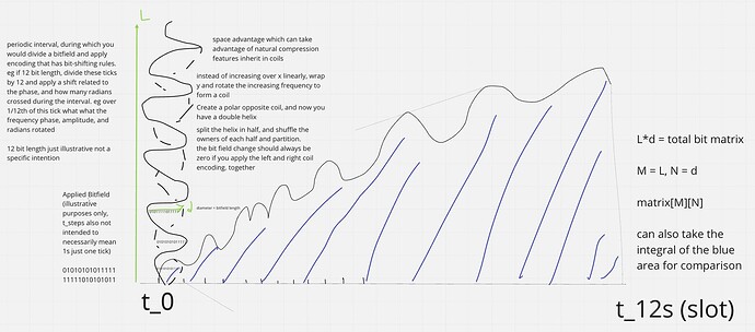
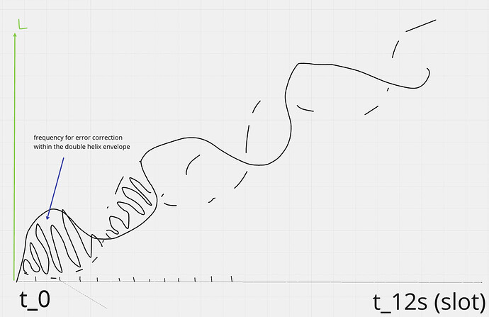
Some diagrams on how this could work
Now each bitfield segment can be checked against many different properties. The envelope must increase by a constant periodic amount, the area of the envelope - the area in the error correction curve, and applying the left and right rotations per period should cancel each other out. You could split the helix over frequency envelope crossing points, and randomly assign others to compare them against such rules without needing to have the whole helix structure. You only need to store half of the helix to generate a full error correction encoding, because the other half is just an inverse, so it can be calculated and then partitioned. Each bitfield encoding has a unique integral solvable area generated by the internally wrapped frequency within the envelope and its periodic step which wraps the bitfield row data.
matrix bitfield row = max length of envelope diameter = d or M
num of envelopes in data block = number of rows = L or N
total data size = matrix[M][N]
If the envelope is always constant over an interval period, eg 12s. Then it can just be represented using a trig func instead of having to be stored in full.
trig(x,y,z,t) → governs where data space is
The internal frequency t_range = (t_start, t_end) as a subset of the full envelope t_env_range.
error_encoding_freq = dataFn(trig(x,y,z,t), trigPhaseShiftFn(x,y,z,t_range))
Store 010101… by default or whatever is the most likely data pattern that can be represented periodically. eg 011011…, or 110011… would do the same. If you have all the data for the total N rows, you can optimize a constant starting row that results in the least amount of phase shifts needed, and thus adds data compression. Each partition will then be given this row value for the N rows over M. One data integrity check can be the number of phase shifts applied in a t_range or what the total phase shift space size should be. And also each point can be compared to the next for relative phase difference and since each bit in the bitfield has a wrapped max, min governed by the envelope divided by the length of bitfield, there should be a predictable binary answer for the next bit, eg where your internal frequency crosses the double helix boundary.
Use a phase shift to flip a bit, or combine with frequency + phase for two bit flips. This lets you generate a frequency that can in worst case require ~N data, and in best case where it’s the default 0101, requires only one row value N to store if all the others over the time period M are identical (since it’s implied by design). So you only need to find the phase shifted data spaces to have the full data represented. Every matrix row now should equal the same starting value independent of row position in the helix when you apply the data and polar inverse phase frequencies together in that t_range.
You can compare any envelope’s phase shifts to others and combine that with other mathematical checks and statistical properties of how you distribute envelope partitions to validator groups to create a system with high data integrity checking & data compression properties.
You can also now take advantages of properties per envelope total phase shift size
encode_count_per_envelope is bound by
MaxP max phase shifts needed by any envelope over the t_range
MinP min phase shifts needed by any envelope over the t_range
EC encode_count_per_envelope
MaxP <= EC <= MinP
MaxP * EnvelopeCount <= Total EC Sum <= MinP * EnvelopeCount
Sum the encode_count_per_envelope over t_range, and that’s the total data space needed to encode your data. Any violation in any of the properties is how you can check data integrity. The more periodic element dimension & space properties you can add reference points the more efficient you can make it.


