I made poc for proof aggregation using GKR
refer to Recursion: Internal vrs External proofs - HackMD
Background
General
In this protocol, GKR used function f_{r_i}^{(i)}(b, c) = \widetilde{add}_i(r_i, b, c)(\widetilde{W}_{i+1}(b) + \widetilde{W}_{i+1}(c)) + \widetilde{mult}_i(r_i, b, c)(\widetilde{W}_{i+1}(b) \cdot \widetilde{W}_{i+1}(c)) .
\widetilde{W}(b, c) is function that returns node’s calculation result in the arithmetic circuit.
Re-construct arithmetic circuit
r1cs file has constraints that has A * B = C form inside. For reconstruction of the arithmetic circuit, make two nodes that represent A * B and C * (-1). And make addition node for these two nodes. That node’s value will be 0. Naively, put a new node from one constraint repeatedly.
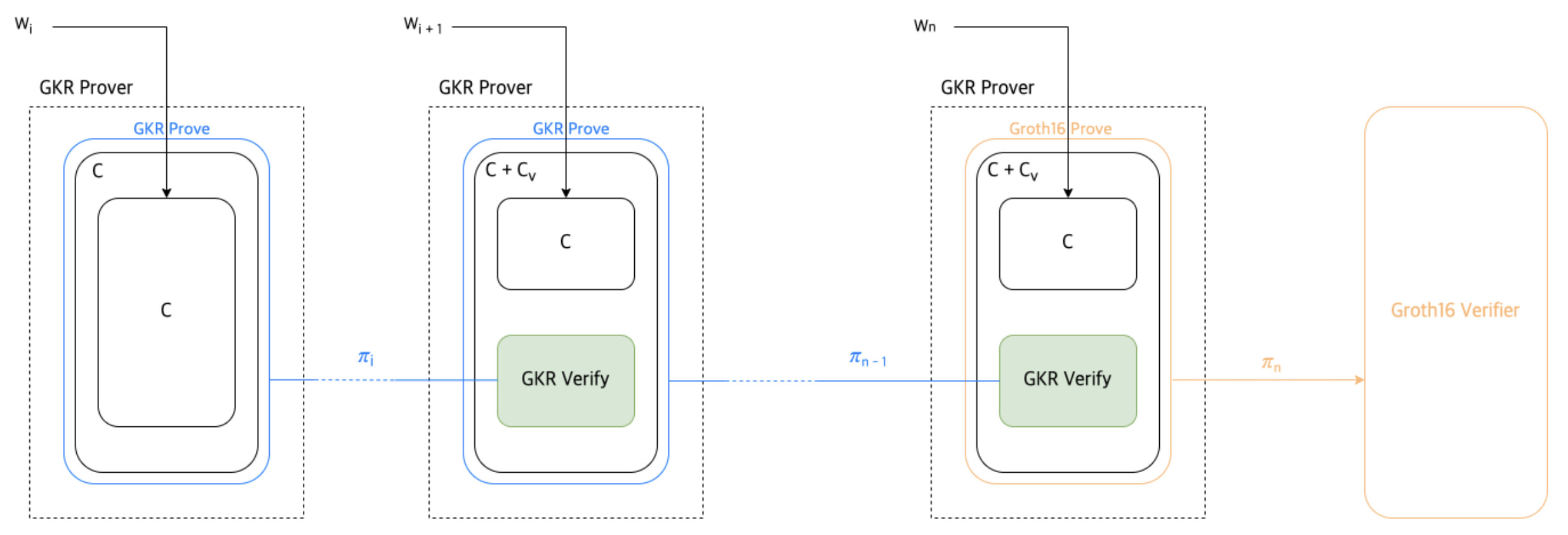
Structure
For each step in recursion, aggregator makes a new circuit from circuit that can verify previous proof and original circuit. And then generate proof from that circom file (exactly, from .r1cs and .wtns file)
Initial round
Parse r1cs file and convert it to GKRCircuit. (Let’s call this C_0)
Get input from input.json.
Calculate all nodes value \widetilde{W}(b, c) by circuit and input.
Make proof \pi_0 from Input and GKRCircuit.
Iterative round (0 < i < n)
There are two circuit C_i and C_{v_{i - 1}}. C_{v_{i - 1}} is circuit that can verify C_{i - 1}.
C_{v_i} can be different form for each circuit C_i. If use same circuit for all C_i, then C_v will be same circuit.
To make aggregated proof for previous proof and current round’s proof, we need
- input (for C_i)
- proof \pi_{i - 1}
Make integrated circuit C'_i.
Use those inputs, make proof \pi_i.
To be specific, input and proof \pi_{i - 1}
Last round
Also there are two circuit C_n and C_{v_{n - 1}}. To send aggregated proof to on-chain verifier, we can use groth16 prover in snarkjs.
Integrated circuit C'_{n} can be proved with snarkjs also.
So final proof \pi_n is groth16 or plonk proof
why I made this
I implemented gkr verifier in circom. but it can verify only one proof and cannot make recursion.
gkr verifier in circom (verifying circuit) can verify gkr proof but it can generate only groth16 and plonk proof by snarkjs.(It is so-called proof composition) Internal gkr proof cannot be made from that circom circuit.
So there were two options.
(1) Implement new circuit representation and re-implement gkr verifier in that representation
But it was too hard to implement verifying circuit from arithmetic circuit.
(2) Implement conversion from circom circuit to gkr circuit
If this is done, gkr verifier in circom can be converted to gkr circuit. And also we can reuse implemented circuit in circom. So I chose (2).
Benchmark
I verified aggregated external groth16 proof that is generated from 3 input sets.
Intermediate proofs(gkr proof) are verified in the aggregated (newly generated) circuit.
First intermediate proof was 17KB. Second intermediate proof was 1.6MB.
It takes 55s to prove two input sets and generate proof (release build) + groth16 proving time is 2s. (Macbook pro M1 8 cores)
(takes 16s in Ryzen 5900 12 cores)
But tried to aggregate one more, it took a very long time (couldn’t get result) because intermediate proof size was too big.
Much more optimizations should be applied to.
Further works
I think it is enough for poc, and other optimizations will be large works (applying Doubly Efficient Interactive Proofs for General Arithmetic Circuits with Linear Prover Time, circom circuit optimization, optimization during conversion from r1cs to gkr circuit, applying FFT). + It has security issues like initial randomness and others.
If you have any ideas for optimization or any others, please let me know. It would be great help.