Signature Merging for Large-Scale Consensus
Authors: George Kadianakis, Dmitry Khovratovich, Zhenfei Zhang, Mary Maller
\cdot
Many thanks to Jeremy Bruestle, Vitalik Buterin, Srinath Setty and Arantxa Zapico!
\cdot
In this post we focus on tools to perform massive-scale signature aggregation for Proof-Of-Stake blockchains.
We first present the bitfield merge problem in the context of the Ethereum consensus protocol. To solve it we introduce a new signature aggregation technique called Signature Merge and demonstrate how it can be used in Ethereum. We then provide three instantiations of Signature Merge using Proof-Carrying Data (PCD) techniques via recursive SNARKs and decentralized proving. Alongside these approaches, we highlight open research challenges related to the scalability of PCD constructions. To close off, we offer preliminary performance evaluations to give readers a glimpse into the expected efficiency of these schemes.
Introduction
Proof of Stake (PoS) systems essentially are open ballot voting systems where validators need to come to consensus. In those consensus systems, cryptographic signatures act as ballots. Validators publicly show their agreement by signing the same message.
We want to enable future PoS systems to operate in massive scale with potentially millions of voters, as required by Ethereum’s Single Slot Finality scheme. In such big P2P systems it’s essential to optimize the way these signatures get collected.
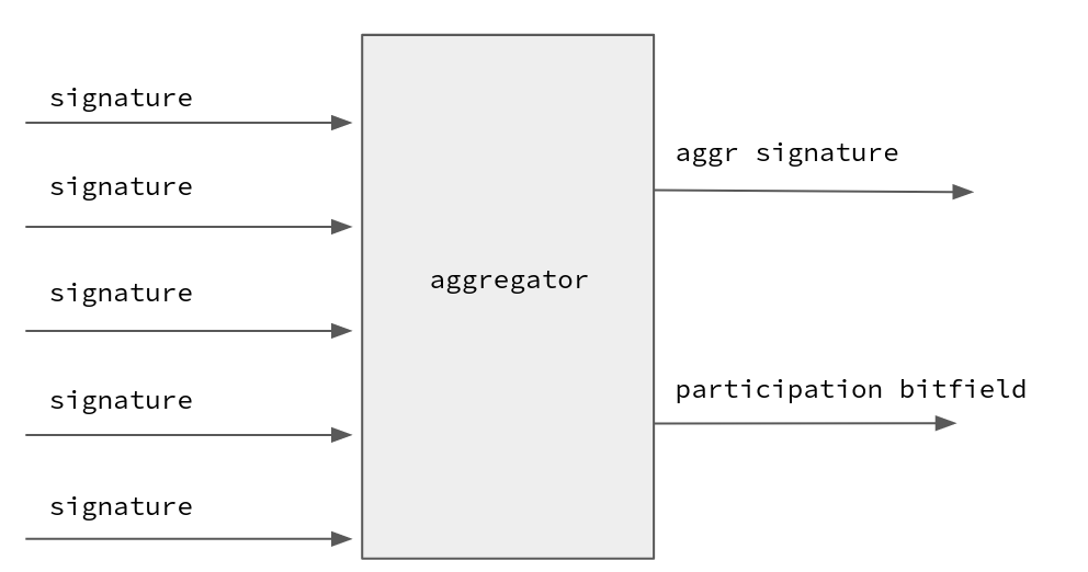
Signature Aggregation
Signature aggregation schemes allow multiple signatures to be combined into one. Aggregation significantly reduces the communication and verification overhead of the system even with a vast number of validators. A famous such scheme is the BLS signature scheme.
Using BLS, signatures can be easily aggregated, but tracking the identity of the signers requires another layer of representation - this is where Ethereum uses bitfields. These bitfields act as a sort of ‘participation list’, marking who among the validators has signed the message. Bitfields are a binary representation of a participants list: ‘1’ at index i means that validator at index i signed the message.
Knowing the identity of the participants is essential for the Ethereum consensus because of slashing, staking rewards and the inactivity leak.
The Bitfield Merge Problem
Consider a signature aggregation system where a collector entity needs to aggregate two aggregated signatures and their bitfields. Aggregating the signature is easy, but merging the bitfield can be tricky.
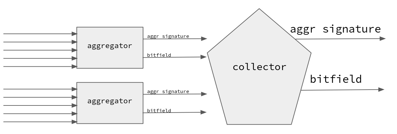
For instance, consider two bitfields: 110 and 010. Merging them isn’t as straightforward as summing numbers. The latter would result in 120, a value that isn’t binary and is twice more expensive to send over the network.
Furthermore, the BLS verifier must know how many times a signature has been aggregated during verification, so that she can compute the correct verification key. That is, the aggregated signature behind 120 has a different verification key from the signature behind 110.
The Bitfield Merge Problem in Consensus
The above issue is encountered in tree-based aggregation topologies as discussed in the Horn proposal, when aggregating already aggregated signatures in the tree’s upper sections.
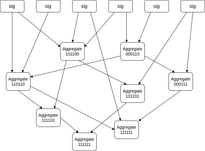
The issue can also be seen in gossip-based aggregation topologies where aggregations are gossiped in a chaotic non-deterministic fashion, as seen in the figure below and was suggested in the past by Vitalik. For networks with a big number of validators but a small number of networking nodes, gossip-based aggregation can be more efficient than a tree-based structure: in such a setting if Alice has 1000 validators she can start the protocol with a populated bitfield of weight 1000 without any prior communication. Furthermore the unstructured property of gossip-based approach can allow more privacy-friendly aggregation protocols.
Due to bandwidth being a fundamental scaling factor in P2P systems, we want to keep using bitfields to denote participation since using heavier representations causes further strain on the networking layer.
We call merging the operation of accumulating two bitfields and producing a bitfield.
In this post we propose Signature Merge schemes as a solution to the bitfield aggregation problem, and three possible instantiations using SNARKs.
Signature Merge schemes
A Signature Merge (SM) scheme supports the recursive merging of signatures and their bitfields while still allowing the extraction of the signer set out of them. In this section we present the interface of an SM scheme, and in Appendix A we show how it can be used in the context of Ethereum.
Following the steps of [GV22], SM schemes are similar in terms of functionality to classic signature aggregation schemes but they introduces the Merge , MergeVerify and GetSigners algorithms.
Additionally, the MergeVerify function does not take as input specific verification keys. Instead it has oracle access to a PKI system which can be queried to retrieve verification keys using a user’s index or a participation bitfield. The PKI system is updated with every call to Keygen.
Finally, the GetSigners method returns a bitfield containing the signers of a merged signature.
A Signature Merge (SM) Scheme has the following algorithms:
-
Setup(1^\lambda) \rightarrow pp: Outputs public parameters pp which are implicitly given to all algorithms
-
Keygen(1^\lambda, \text{PKI}) \rightarrow (\text{sk}, \text{vk}, k): Generates secret signing key and public verification key for a user and registers the public key to the \text{PKI}. Also returns the user’s index k in the \text{PKI} system.
-
Sign(\text{sk}, m) \rightarrow \sigma: Takes as input a signing key sk and a message m and computes a signature \sigma
-
Verify(\text{vk}, \sigma, m) \rightarrow 0/1: Takes as input a verification key \text{vk}, a message m and a signature \sigma and returns whether the signature is valid or not.
-
Aggregate^\text{PKI}(m, \{ ( \sigma_i, k_i ) \}_i) \rightarrow \pi : The aggregation algorithm takes as input a sequence of signatures \sigma_i with user PKI indices k_i and outputs a merged signature \pi. It also has access to a PKI system which can be queried to retrieve any verification key.
-
Merge^\text{PKI}(m,\{ \pi_i \}_i) \rightarrow \pi: The merge algorithm takes as input a sequence of merged signatures \pi_i and outputs a merged signature \pi. It also has access to a PKI system which can be queried to retrieve any verification key. Note that
Mergeallows us to combine merged signatures \pi_i without knowing any of the underlying individual signatures \sigma_i. -
MergeVerify^\text{PKI}(m, \pi) \rightarrow 0/1: The merged signature verification algorithm takes as input a message m and a merged signature \pi and outputs whether the signature is valid or not. It also has access to a PKI system which can be queried to retrieve any verification key.
-
GetSigners^\text{PKI}(\pi) \rightarrow b: Given a merged signature \pi, return a bitfield corresponding to the indices of all the signers who participated.
Note that merged signatures must have size linear to the number of signers, otherwise the GetSigners method would not be able to recover all the signers of a merged signature, violating incompressibility.
We say that a Signature Merge scheme is lightweight if the size of \pi is minimal: it only uses a single bit for each user of the PKI system. In this post we concern ourselves only with lightweight Signature Merge schemes.
Security of Signature Merge Schemes
Security of SM schemes is defined similarly to aggregation schemes. Let i denote the index of an honest signer. An SM scheme is unforgeable if no polynomial time adversary can produce verifying (m, \pi) such that b = \mathbf{GetSigners}^\text{PKI}(\pi) and the ith bit of b is equal to 1 (b_i = 1), unless party i has previously signed m.
Signature Merge Instantiations
In the upcoming sections, we provide a primer on recursive SNARKs and PCD, followed by three distinct methodologies to materialize a Signature Merge scheme via different recursive SNARK paradigms.
Proof-Carrying Data using Recursive SNARKs
Recursive SNARKs are cryptographic proof systems where the SNARK verifier is succinct enough to be evaluated inside another SNARK circuit. This ‘nesting’ can be performed repeatedly, allowing for an aggregation of multiple proofs into one.
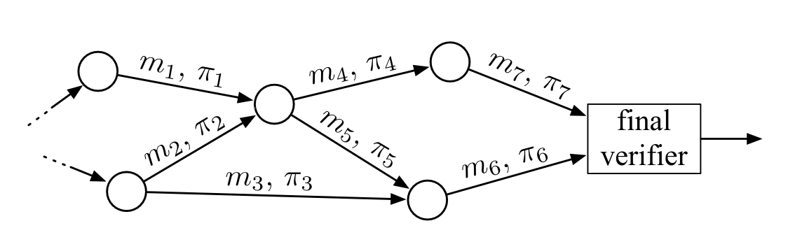
When combined with the Proof-Carrying Data (PCD) paradigm, we can start thinking of the participation bitfields as the main object of our Signature Merge system. The bitfields, depicted as m_i in the figure above, always travel with associated proofs, depicted as \pi_i. A receiver can verify the proof, and be convinced that the bitfield is the product of a series of valid signature verifications and bitfield merges.
Approach 1) Recursive STARKs
In this section we present a straightforward Signature Merge scheme based on recursive STARKs.
The approach is based on a recursive STARK circuit that consumes signatures or other STARKs alongside their associated bitfields. The circuit verifies every signature and STARK received and merges their bitfields. The circuit’s output is the merged bitfield and the STARK proof.
While this is not the most efficient of our suggested approaches, it’s the conceptually simplest approach and also offers post quantum guarantees.
Here, a STARK is a hash-based proof of a polynomial equation, which encodes a certain computation. A recursive STARK is specific in that the computation contains the verification of other STARKs. Therefore, the Merge step consists of the following:
- Verifying the incoming STARK proofs with their own bitfields.
- Creating a STARK proof that the incoming proofs are valid and the union of their bitfields equals the alleged result. This step requires constructing a number of Merkle trees that hash in the entire computation trace, i.e. the verification of STARKs and unionizing the bitfields.
- Publishing the STARK proof, which contains of a number of openings in the just-constructed Merkle trees.
The recursive STARK circuit
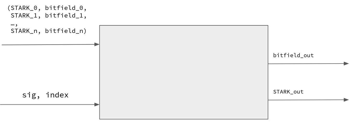
Using a simple and slim hash-based signature scheme (e.g. Winternitz) instead of BLS, we introduce the following recursive STARK relation:
- Public inputs: Root of all pubkeys R, public bitfield b, message hash m
- Private inputs: N STARKs with N bitfields, and optionally a signature along with a participant index
- Statement:
- Recursive STARK verification: For all 1 \le i \le N, the i’th provided STARK is a valid STARK of this statement using the i ’th bitfield and the same R and m
- Signature verification: If a signature is provided, check that it’s a valid signature of m with the pubkey at the position defined by the participant index in the pubkeys tree rooted in R
- Bitfield union: The public bitfield is the union of all the bitfields in the STARKs, with 1s filled in for each of the m indices for which we have individual signatures
The circuit is informally depicted above to demonstrate how the recursion works (observe how the inputs match the outputs).
Approach 2) Recursive Halo2 (atomic accumulation)
A computationally cheaper approach compared to full recursion would be to use an atomic accumulation scheme like the original Halo construction.
The approach here is similar to full recursion in that we still verify proofs inside SNARKs, but the Halo approach is lighter for the prover: Halo only implements the lightweight part of the verifier inside the SNARK, while deferring any expensive operations. These operations get deferred to the end of the recursion chain.
Halo2-IPA
The original Halo paper was written on top of the Sonic arithmetization scheme, but we can adapt the protocol to a modern Plonkish based scheme and use IPA polynomial commitments to perform the final polynomial vanishing argument. This is exactly what zcash has done with halo2, but we also need it to support deferred recursion.
Note that in halo2, the most expensive operation of the verifier is verifying IPA openings. Using the techniques from Halo we can defer the expensive in-circuit MSM needed when verifying the IPA opening proofs. At each recursive step, we defer this expensive operation and accumulate it into an accumulator. Finally, when we need to pass the proof to the next person, that person must verify both the proof and the accumulator.
Furthermore, we also need to adjust the scheme to implement Proof-Carrying Data but fortunately the “Proof-Carrying Data from Accumulation Schemes” paper provides a construction we can use for benchmarking purposes.
The Halo PCD circuit
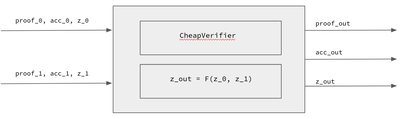
Now let’s dig deeper into how the Halo PCD circuit looks like. For this section, we will be considering recursive circuits that verify two proofs, essentially allowing PCD with a binary tree structure.
The circuit takes as input two tuples (\pi_0, acc_0, z_0) and (\pi_1, acc_1, z_1). Where (\pi_0, acc_0) is the first IPA proof and its accumulator, while z_0 corresponds to the useful inputs to the circuit. For example, z_0 can be seen as a tuple (\sigma_0, b_0) where \sigma_0 is an optional signature, and b_0 is a bitfield.
Note that in Halo2, the entire proof system gets reduced to a single IPA proof. Also, note that both the proof and the accumulator have the same form: they are both IPA proofs.
Our PCD circuit has two tasks:
- Cheap-verify the proofs and accumulators (\pi_0, acc_0) and (\pi_1 ,acc_1), while accumulating the expensive MSM operations into acc_{out}
- Perform the useful computation function F given the inputs z_0 and z_1:
- If a signature was provided, verify the signature.
- Return the union of the provided bitfields.
Below you can see an informal rendition of the circuit:
Note that in real life, the circuit could look different. For instance, maybe the circuit doesn’t output the accumulator, it just checks its validity, and the accumulator is computed out-of-circuit.
Approach 3) Folding (split accumulation)
The other end of the spectrum is the recent line of work on folding. Folding allows us to replace the expensive in-circuit SNARK verifier, with a much simpler folding verifier. This significantly decreases the prover’s computational overhead of recursion since no proof verification actually happens inside the circuit.
The folding process deals with witnesses W to a certain structure \mathcal{S} and instances U. The structure in the original Nova is a set of matrices that define an R1CS relation; later on this is generalized to CCS (higher-degree constraints) in Hypernova and to polynomial equations in Protostar. The witness is a set of values satisfying the structure equations (i.e. R1CS constraints in Nova) and instance is a commitment to the witness plus some metadata. We note that the actual structure is not exactly R1CS but a more general relaxed R1CS, where certain error terms are introduced.
The actual folding is a procedure to compute the folded witness W_{folded} out of l input witnesses W_1,\ldots, W_l, then to compute cross terms T from the same witnesses, and finally to compute folded instance U_{folded} from input instances U_1,\ldots, U_l and T. The entire procedure is done in the challenge-response fashion, which guarantees that W_{folded} satisfies U_{folded} only if for each i there exists a W_i satisfying U_i.
To make an IVC, the prover creates a circuit \mathcal{S}' that encompasses both the last step of the folding process (which does not depend on the witness size) and the useful computation F, plus some extra hashing steps that bind together instances and the IVC inputs-outputs. Then the witness W' to this circuit is committed to in order to create a new instance U'. Having required that the instances to be folded have the same structure, i.e. \mathcal{S}'=\mathcal{S}, then U' can be folded with U at the next step of IVC.
Folding schemes have smallest recursion overhead, but they also come with a variety of open research questions that we discuss below.
Moving Nova to PCD
Nova as depicted in the original paper is tailored for IVC chain-like computations. In contrast, Signature Merge requires a PCD graph-like structure with nodes accepting arbitrary proofs from other nodes with no clear global order.
Adjusting Nova for PCD requires us to introduce an additional instance-witness pair into the circuit \mathcal{S}. This results in a more complex S as well as more constraints needed to fold the extra pair.
The same approach has been previously proposed by the Paranova project, noting that it allows PCD using a binary-tree structure.
Minimizing the curve cycle
Both folding and recursive Halo2 require us to compute elliptic curve operations inside circuits. This can be done using non-native arithmetic or using cycles of curves. Most projects rely on cycles of curves since non-native arithmetic is many orders of magnitude more expensive than normal arithmetic.
However, using cycles of curves results in a complicated system as proofs need to be produced in both curves and they need to be correctly linked and verified.
The recent work on Cyclefold is particularly useful in our PCD setting as it can reduce the complexity on the second curve. Using Cyclefold the second curve is only used to assist with scalar multiplications, without needing to perform any of IVC/PCD operations.
Hashing public inputs
The folding circuit necessarily contains hashings of inputs and outputs of IVC together with folded instances. As in-circuit hashing is relatively expensive, we need a way to compress the inputs even further.
Folding lookups
Again, as binary decomposition is too expensive, we seek a way to implement lookups to speed up the OR operation. The problem is that the lookup arguments require a support of certain polynomial equations, and most folding schemes do not support such equations out of the box. We investigate for possible ways of integrating lookups into (Hyper)Nova with minimal impact to definitions and proofs.
Witness size management
In order to perform folding, the aggregator needs the full witness to each folded instance. For a PCD, this makes the witness of each input instance at least as big as the witness for the PCD step function. In our case it is the witness for the OR operation over two 1 mln bit inputs, which requires at least 3 mln bit witness, or 12 K field elements. The folding operation requires several scalar multiplications, which totals to 10-20K witness elements as well. Altogether, a PCD folding prover receives as witness 2-3 MB of data from each of two senders.
Deeper dive into Signature Merge circuits
In this section we dig deeper into some SNARK-related themes that all the approaches above have in common.
All the approaches above have similar functionality: we are dealing with SNARK circuits that verify signatures, and also compute unions of bitfields. In this subsection, we are going to talk about performing these operations inside SNARKs in more detail.
Verifying signatures inside SNARKs
We need to choose a signature scheme that is easy to verify inside SNARKs. We assume that the message to be signed is constant size (approx. 256 bits) being a hash of public value, and varies for each aggregation process. Given that the recursion overhead in all approaches is at least a few scalar multiplications, we can choose from the following variants:
- Schnorr-like signatures: A simple discrete-log based scheme which requires only one elliptic curve scalar multiplication inside the circuit. Similar schemes are based on ECDSA signatures.
- Proof of preimage. Here a signature is a proof of knowledge of secret key k, which is hashed to get public key K= H(k) with H being some hash function. The actual message is part of the context in the proof process. The proof method is chosen to be native for the signature aggregation method, i.e. IPA for Halo-IPA, STARK for recursive STARKs and folding. The costs are mostly determined by the proof method but also dependent on the hash function used in the signature, which should not be too expensive.
- Proof of encryption key. This method resembles the previous one, with the public key K being the encryption of some constant (say, 0) on the secret key k, i.e. K = E_k(0). The actual signature may or may not be the result of the encryption as well, like in the FAEST scheme.
While the choice of the signature scheme might initially seem important, it’s actually of lesser importance since in all recursive SNARK constructions, the SNARK verifier inside the circuit dominates the performance of the scheme.
Bitfield union using lookups
The process of taking the union of two bitfields is a straightforward logic operation, but it does not translate that nicely into the language of arithmetic circuits.
A naive approach would involve decomposing the bitfields into bits, and then working over each bit separately, making sure that the two input bits match the output bit. This means that we have to spend O(logd) constraints, where d is the size of the bitfield.
This seems like the perfect environment to use lookup arguments, which allow us to chunk together multiple bits and spend a single constraint for each chunk.
Consider a lookup table of all possible OR outputs of two bitfields of size 2^5. This means that we can chunk bitfields into chunks of five bits, and use the lookup protocol to perform the union.
Managing circuit size
It’s important to observe how the size of the circuit impacts the above approaches. The bigger the circuit, the more painful it is to recursively verify it.
It’s also worth noting that in many signature aggregation protocols, the protocol will begin by merging tiny bitfields before moving to bigger and bigger bitfields. For this reason, it would be ideal if we only had to pay for what we use: use a small circuit size when working with small bitfields.
This can be achieved by working with multiple circuits: Since the size of the output bitfield is public, the prover can always choose the circuit best suited to the size of the input bitfields. This can work very well in tree-based aggregation protocols where the bitfield sizes and the provers are known in advance.
Another approach is chunking up the statement that is proven: Instead of working with the full bitfield, work with smaller chunks at a time, and produce multiple proofs when needed. At the beginning of the protocol, the provers will be dealing with small circuits and producing a single proof, but as the protocol goes on and the bitfields grow, the provers will need to produce multiple proofs per bitfield, and hence the recursion overhead will grow.
Performance evaluation
In this section, we aim to give you a sense of what to expect in terms of performance for the discussed schemes.
It’s important to note that obtaining precise figures without fully implementing the schemes is challenging, especially given the presence of unresolved questions.
We start with an overview presented in the table below, and then delve into each scheme individually.
Merge cost |
MergeVerify cost |
Communication overhead | |
|---|---|---|---|
| Recursive STARKs | Bad | Very Good | Bad |
| Recursive Halo2 | OK | OK | Good |
| Folding | Good | OK | Very Bad |
Performance Evaluation: Recursive STARKs
While it’s hard to get reasonable benchmarks for the recursive STARK scheme without an implementation, in this section we present benchmark data provided by the RISC0 team who are using STARK recursion in alternative applications.
While the RISC0 benchmarks are certainly useful, it’s worth pointing out that designing a custom circuit precisely for our use case would allow us to tweak the various parameters of the system (e.g. hash function, finite field, security params, etc.) and the actual numbers could look wildly different.
In Appendix B, we present a work-in-progress draft for a formulaic approach to evaluating the prover performance of recursive STARKs.
Merge cost
In terms of API, in this section we will be considering the costs of the Merge() function of a Signature Merge scheme (i.e. merging two bitfields together).
The RISC0 prover currently spends 2.5 seconds to recursively verify 2 STARKs inside a circuit. This effectively allows N = 2 in the circuit above, and enables a binary “proof tree” structure which is common in PCD applications.
The RISC0 system aims for 100-bit of security and the majority of the prover’s time is spent on hashing the full witness. The figure above comes from a prover equipped with an Nvidia A4000 GPU, which is specialized hardware that validators normally don’t have.
The RISC0 team believes that by further optimizing their GPU implementation and their algorithms, they can get up to 4x improvement in the prover speed in the next years (potentially bringing the cost of Merge to below a second).
RISC0’s circuit is proving RISC0 VM instructions whereas our circuit is verifying signatures and merging bitfields. From discussions with the RISC0 team, we believe that the underlying application is not so important, because the large STARK verifier circuit dominates the prover’s performance.
MergeVerify cost
Super fast! A few miliseconds.
Communication overhead
The STARK’s proof size comes to about 300kb (depending on the security parameters), which is quite big.
Performance Evaluation: Recursive Halo2
In this section, we will be considering participation bitfields of size 1 million bits. This means that they can be expressed using 2^{12} field elements. We estimate that the final circuit will have size about d = 2^{16} since it needs to at least process the two input bitfields.
Merge cost
The prover time in this scheme is the time it takes to perform the useful computation (i.e. merge bitfields or verify signatures), plus the time it takes to recursively verify any proofs provided.
Prover time for useful computation:
- Signature verification: 200-2000 R1CS/(low-degree Plonkish) gates
- Bitfield union:
- Plain: 2^{21} gates (degree-2) for binary decomposition and 2^{20} gates for the union operation.
- With lookups: 1 gate per 8x8 bitwise OR: 120K gates and table of size 64K entries.
Recursive overhead (essentially the runtime of algorithm \mathbb{P} from section 5.1 of the “Proof-Carrying Data from Accumulation Schemes” paper):
- Deferred IPA verification for all proofs and accumulators (\pi_0, acc_0, \pi_1, acc_1):
- 4 \cdot 2 \cdot logd = 4 \cdot 2 \cdot 16 = 128 ECMULs
- 4 \cdot 2 \cdot logd = 128 ECADDs
- 4 \cdot logd = 64 hashes
Finally, let’s compute the total recursive circuit size:
- Assuming a 8-bits preproceessed lookup table, the bit field union circuit can be implemented within 2^{20-8} = 2^{12} constraints.
- Using Jellyfish’s custom gate, each ECMUL takes 300 plonkish constraints, each poseidon hash takes 200 plonkish constraints. The deferred IPA verification circuit can be implemented within 51200\approx 2^{16} constraints.
The recursive circuit size is therefore estimated at 2^{16} constraints.
Using the Pallas/Vesta curves, such a circuit can be proven in about 1.6 seconds on a high end desktop. If we were to use GPUs, the proving could be performed in 0.35 seconds.
MergeVerify cost
In terms of API, the MergeVerify() function of a Signature Merge scheme corresponds to the accumulator’s decider functionality.
The decider needs to perform two MSMs, one for each side of the curve. The MSM’s size equals to the circuit size, i.e., 2^{16} if we use lookups.
Each of those MSMs can be performed in about 200ms using a decent modern laptop, or in 51ms using a high-end m6i.8xlarge AWS instance.
Communication overhead
The communication overhead of the Halo approach basically boils down to sending a Halo2 proof and an accumulator. Here is an informal breakdown of the sizes:
- Halo2 proof size:
- For each witness column:
- Commitment (G point)
- Opening value at random element (1 field element)
- IPA opening proof (2 log n group elements, 1 field element)
- For each witness column:
- Accumulator size:
- Commitment (G point)
- Opening value at random element (1 field element)
- IPA opening proof (2 log n group elements, 1 field element)
where n is the circuit size (in our case around 2^{16}).
All in all, the communication overhead depends on the circuit structure (the number of witness columns). We believe that the actual communicaton overhead will be between 5kb and 15kb, where the latter figure is for a circuit with 13 witness columns.
Performance Evaluation: Folding
Evaluating the performance of the folding PCD scheme proved to be the most challenging task, mainly due to the open research issues surrounding folding and distributed prover PCD.
In the following section, we provide a preliminary assessment to initiate the evaluation process.
Merge cost
The Merge operation is dominated by two tasks:
- Computing the cross term – an MSM of size C, the circuit size.
- Computing the instance for the witness of the folding process – the same size MSM.
So essentially 2 n-sized MSMs.
The cost of running the useful computation function F will depend on howe folding lookup schemes will end up looking like.
MergeVerify cost
Verifying that the folded witness satisfies the folded instance is essesntially another n-sized MSM.
Communication overhead
As discussed in the “Witness size management” section, we expect the witness size that needs to be sent to the next prover to be in the order of 2-3MB for a bitfield of a million bits which is huge compared to the other approaches.
Future work
We welcome contributions in the following problems:
- Writing detailed specification of the PCD circuits for any of the three approaches
- Implementing any of the three approaches so that we can get more precise benchmarks
- Tackling the open research questions posed in the folding section
- More work on signature aggregation topologies for Ethereum
Get in touch if you are interested in working on the above!
Appendix A: Using a Signature Merge scheme in Ethereum
Consider a gossip-based aggregation scheme:
Start of aggregation protocol (Signature phase):
- Alice creates a sig with
Sign()and sends it to Bob
Next phase of aggregation protocol (Aggregation phase):
- Bob verifies signatures with
Verify() - Bob has received a bunch of sigs and uses
Aggregate()to create a merged signature \pi - Bob sends \pi to Charlie
Next phase of aggregation protocol (Merge phase):
- Charlie verifies merged signatures with
MergeVerify() - Charlie has received a bunch of merged sigs and uses
Merge()to create a merged signature \pi - Charlie sends \pi to Dave
[Merge phase repeats…]
Final phase of aggregation (Post to block):
- Dave sends his best merged signature \pi to the global topic (using the weight of
GetSigners()to pick the best signature) - Peter the proposer monitors the global topic and finds the best merged signature
- He verifies it with
MergeVerify()and puts it on the block - He uses
GetSigners()to assign rewards to participating validators
Appendix B: Performance estimates on STARK recursion
For given security level \lambda let \phi_{\lambda}(m) denote the number of hash calls needed to verify a STARK for a program that computes m calls to 64-bit hash function Rescue/Poseidon (they have similar witness size). Then the proof size equals 32\phi_{\lambda}(m) bytes. A verification circuit for checking a single STARK proof then computes \phi_{\lambda}(m) hashes. In order to recurse N STARKs and keep the verification circuit constant size, we need
Figure 7 from the Starkware specification suggests that \phi_{100}(m)\leq 150 \log_2 m. Thus we need m such that \frac{m}{\log_2 m}>150N. For N=2 we can choose m=2^{12} and \phi_{100}(m)\approx 1500.